High-pressure common-rail injection technology has revolutionized the diesel industry. Over the last decade, it has allowed engine builders to run higher injection pressures (as much as 29,000 psi in the new LML Duramax and 6.7L Power Stroke) in order to increase efficiency, while greatly reducing emissions. Use of the common-rail system has also facilitated multiple injection events (making diesels quieter).

The icing on the cake is that these cleaner-burning engines make much more power than their predecessors. In the case of the ’01-to-’10 Duramax and ’03-to-present Cummins, the heart of the common-rail system has been the Bosch CP3. Unlike previous (pre-common-rail) injection pumps, it has fewer tasks to perform. The CP3 injection pump’s sole job is to create and regulate high-pressure fuel (it’s not timed with the engine’s crankshaft and camshaft). The fact that the CP3 came from Bosch’s heavy-duty line of injection pumps also speaks to its great reliability, as it was designed to play a vital role in million-mile engines.
Low-Pressure Circuit In order to talk about the modified injection pumps available in the aftermarket, which feature increased displacement (i.e. Stroker pumps), we first have to understand the CP3 pump’s functionality.
Bosch Cp3 Troubleshooting
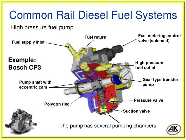
This diagram (which shows the low-pressure fuel circuit on the right side of the pump) is similar to what you’d see in a Bosch CP3.3 NH pump, which is the model used on an LBZ Duramax. First, low-pressure fuel enters the gear pump (A). The gear pump’s purpose is to feed the high-pressure pump. The maximum flow rate of the gear pump is limited by the calibrated suction throttle (B) to avoid an overload scenario at the overflow valve (C). The overflow valve returns fuel to the gear pump inlet, provides lubrication for the pump, and keeps pressure in front of the metering unit (D) constant.
Isuzu fts 750 owners manual. The metering unit, also known as the MPROP, FCA, or fuel pressure regulator, regulates the maximum flow rate the CP3 delivers to the rail. The zero delivery throttle (E) exists for instances in which no additional fuel is required in the rail. It routes diesel that is designed to leak out of the metering unit (when it’s in the closed position) away from the plungers in the pump and back to the gear pump inlet. Stroker Pump Ingredient 3: Suction Valves One component that substantially limits fuel flow in stock form is the suction valve. Fortunately, it’s another area where added stroke helps out greatly. When you compare the suction valve in both of these photos, you can see the one on the right sits further away from its seat. Because the suction valves are responsible for allowing fuel into the cylinders, stroking them provides much more flow.
Bosch Injector Pump Rebuild
One of the drawbacks here is that the valve seat wear increases (causing the suction valve to wear out sooner)—and while the pump will still last a while, longevity is sacrificed. Stroker Pump Ingredient 4: Metering Unit Modifying the metering unit (also known as the MPROP, FCA, or fuel pressure regulator) is very common because it’s responsible for the quantity of diesel that feeds the high-pressure side of the pump. It regulates the flow to the high-pressure pump, and ultimately the injectors. Porting the valve piston on the metering valve is a typical means of modifying it, but other proprietary modifications may also exist.
The end goal is to keep the plungers as full of fuel as possible, yet still be able to regulate it.
Covers: Bosch PE(S)-6MW Fuel Injection Pump Pages: 50 Format: PDF file File size: 1mb Compatibility: Windows/Mac/Tablet Note: Instant digital download only – no printed copy or CD-ROM media. This repair manual contains specifications and repair procedures for the Bosch PE(S)-6MW Fuel Injection Pump. View the repair manual on your computer or print off detailed specifications, service instructions, including illustrations, as needed. Inside this manual you will find all the detailed information needed to correctly perform maintenance and repairs. Topics in the Bosch PE(S)-6MW Injection Pump Repair Manual: SECTION 1 – GENERAL Description Identification Operation Principles Fuel Flow Metering Pump Features Governor Nozzle Nozzle Holder Specifications Service Tools Torque Chart SECTION 2 – DISASSEMBLY Preparation Exploded View of Pump Exploded View of Governor Governor Disassembly Pump Disassembly SECTION 3 – CLEANING AND INSPECTION Inspection Chart Governor Adjustment SECTION 4- REASSEMBLY Pump Reassembly Governor Reassembly SECTION 5 – CALIBRATION Calibration Stand Maintenance Procedure Data Sheets and Calibration Charts Pump Part No.

1 802 608 C92 The Robert Bosch Model PE(S)-6MW Injection Pump is used on the International DT-466C diesel engine. The injection pump is an in-line, plunger type, with an individual plunger and barrel pumping element for each engine cylinder. The injection sequence is 1,5, 3, 6, 2, 4. The injection pump assembly incorporates mechanical, flyweight type RQV variable speed governor.
The pump throttle lever and the high-speed stop screw are located on the left side of the governor assembly. The fuel shut off lever is also located on the left side of the governor. The injection pump is located on the left side of the engine. High pressure lines connect the pump to the nozzles. Example Repair Manual content (actual manual may vary): How does this work? It’s simple – after purchasing this manual through our secure checkout, a download link will be sent to the email address you specify at checkout.
You have up to 30 days to retrieve and save the file. Once saved, the manual is yours for good.
Have any questions or need more details? Related products.